
QTR 8RC
INR 0.00
Shipping Charges : (+) INR 49.00
Shipping Days : 7 days
Product/Service details
Specifications
Description
Functional Description
The QTR-8RC reflectance sensor array is intended as a line sensor, but it can be used as a general-purpose proximity or reflectance sensor. The module is a convenient carrier for eight IR emitter and receiver (phototransistor) pairs evenly spaced at intervals of 0.375" (9.525 mm). To use a sensor, you must first charge the output node by applying a voltage to its OUT pin. You can then read the reflectance by withdrawing the externally supplied voltage and timing how long it takes the output voltage to decay due to the integrated phototransistor. Shorter decay time is an indication of greater reflection. This measurement approach has several advantages, especially when coupled with the ability of the QTR-8RC module to turn off LED power:
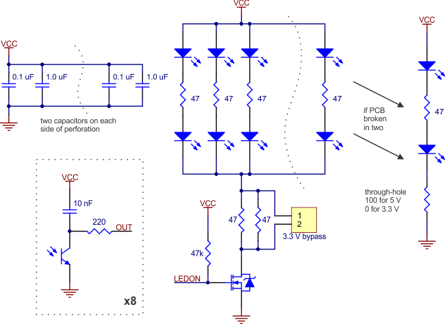
The outputs are all independent, but the LEDs are arranged in pairs to halve current consumption. The LEDs are controlled by a MOSFET with a gate normally pulled high, allowing the LEDs to be turned off by setting the MOSFET gate to a low voltage. Turning the LEDs off might be advantageous for limiting power consumption when the sensors are not in use or for varying the effective brightness of the LEDs through PWM control.
This sensor was designed to be used with the board parallel to the surface being sensed.
The LED current-limiting resistors for 5 V operation are arranged in two stages; this allows a simple bypass of one stage to enable operation at 3.3 V. The LED current is approximately 20–25 mA, making the total board consumption just under 100 mA. The schematic diagram of the module is shown below:
 |
Terms & conditions